Are you tired of listening the loud "builder grade" bathroom fan? Do you avoid operating it
in the early morning or late evening when your spouse is in bed? You can actually FIX this annoyance by installing a
quiet fan.
The typical builder grade bathroom is essentially the same in almost every house on the planet, with the design
dating back to the 80s, if not before. It is usually rated at 4 sones, which is fairly loud. One manufacturer touts this
as an advantage! It affords "privacy" to the person in the bathroom on the pot (by drowning out noises).
Nonetheless, 4 sones won't mask the sound of a well-executed resonant toilet bowl fart!
Exhaust fan noise levels are rated in "sones", which is similar to decibels, except that sones are linear - a 2 sone fan is
approximately 2 times as loud as a 1 sone fan. For decibels, it takes 10dB difference to be heard as twice as as
loud.
The other fan rating of interest is the air movement capacity. This is rated in CFM - cubic feet per minute.
We will be describing the installation of a 50 CFM fan (usually the smallest available). This is the size of the universal
builder grade unit, which is often a Broan/Nutone model 688. This size is fine for most small bathrooms, such as 6 x 8 ft
or 5 x 10 ft. Actually the builder of our house put one of these in the master bath - a much bigger area - although
there was an extra one in the toilet "closet" as well.
So, in this article I will be describing the replacement of a builder grade 4 sone fan with one that is rated at
1 sone! The recordings on the right are the sounds of a 4 sone vs a 1 sone fan. The difference is very apparent.
On a D.I.Y. scale of 1 - 10, the project is about 5. The main difficulty, as with all
home improvement projects, is how difficult it is to remove the old unit.
Hopefully some of the tips and information that I show here will keep the project closer to that 5, or perhaps
less.
NOTE: There is (mostly) nothing to stop you from replacing your fan with a slightly bigger one.
If your bathroom is slightly larger, or if the builder actually used a slightly bigger fan, you could probably use an 80
CFM fan (a common size, available at Home Depot or Lowes). This should fit in the same opening, but might require
trimming about 1/2 on one or two sides of the sheet rock.
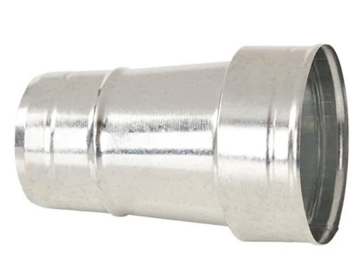
One note: the output opening of an 80 CFM fan or 100-110 CFM fan is 4 inches in diameter instead of the
3 inch opening on the 50 CFM fan. You could use a "4 inch to 3 inch reducer" (shown below) to connect to your existing
3 inch duct, without too much degradation of the air flow. If the existing fan is 80 CFM or more, the duct should already
be 4 inch.
You're good with this scenario as long as the connecting duct is flexible - usually it is.
If you are installing a fan from scratch (not to replace an existing one), I will have soon have a companion article,
describing the intatllation of a 110CFM unit as a room venilation fan.
Click the player to listen to the Builder Grade noisy fan.
Click the player to listen to a much quieter fan of the same size and capacity.
The Equipment
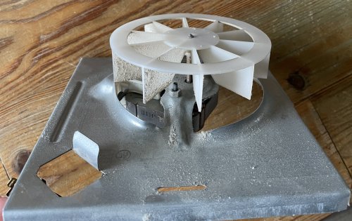
Here is the motor and fan blade of the standard bathroom fan. It is inherently noisy and has to
turn at a fairly fast speed to move any air. That's why it is so noisy.
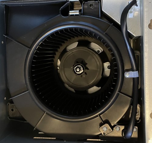
The quieter fans use a "squirrel cage" blower. This can move more air even at lower
rotation speeds.
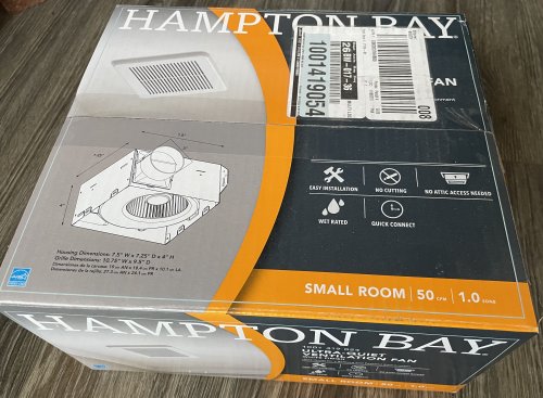
So here is a picture of the "Hampton Bay" 50 CFM fan from Home Depot. Yes,
you may be used to thinking of Hampton Bay as an economy product. But this fan, and a 110 CFM fan
that I bought for another project were both of high quality, and were very quiet.
I am writing a separate article (available shortly) about what I did with the 110 CFM fan. It will be called "Installing
a bedroom exhaust fan". I wanted to be able to pull in more of the fresh sea air in the bedroom at night (when there
is no wind). We are about 1/4 mile from the ocean. If we were right by the ocean, there would NEVER be a
time without wind!
And this is the 4 x 3 reducer that might be necessary if you replace a 50 CFM
fan with an 80 CFM fan.
Before starting, you should locate your circuit breaker box and switch off the breaker that handles
the fan (and probably the bathroom lights).
A note: In most installations, you "should" be completely safe in working on a switched item like a fan
or light assembly, if you just turn off the switch. With the switch off, the black ("hot") wire is disconnected. It wouldn't hurt
to put a piece of tape over the switch. to keep someone from accidently turning it on.
All of this, of course, depends on the house having been wired correctly. So it's your call. . .
Installing your bathroom fan
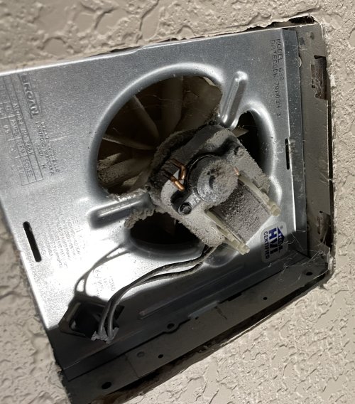
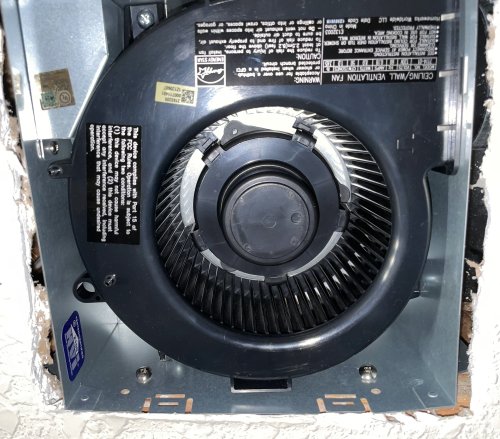
1 Remove the grill by pulling it down and then squeezing the
spring holders together. Here is the exposed existing fan; sure enough, a broan/Nutone model 688.
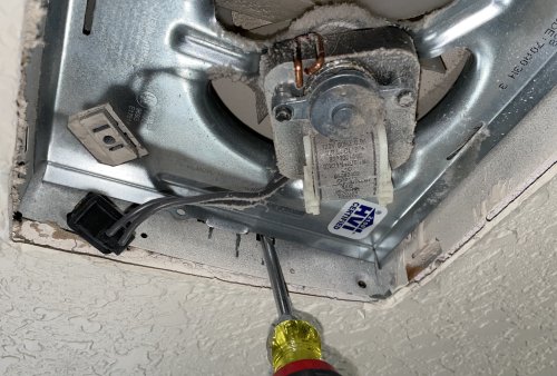
2 First unplug the fan motor as shown.
The fan assembly is just held in place by tabs. Place a flat screwdriver against the housing and pry
against the assembly until the tab falls out of the hole in the housing. (Zoomed in shot showing the tab is
in the next picture.)
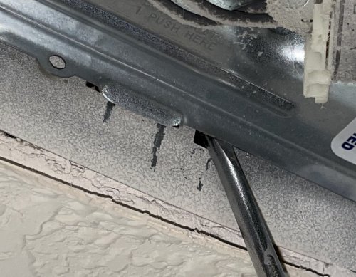
3 A zoomed in shot showing
the tab holding the fan assembly in place.
NOTE: When you pry the tab out of its hole, the fan assembly will essentially just fall on your head!!
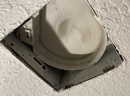
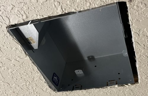
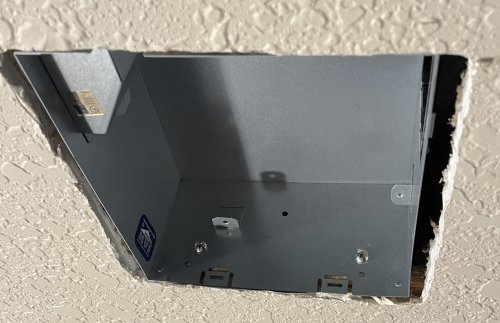
4 Here's the empty fan housing. It has
been partially sprayed white during the construction of the house, just like all the black and white wires in the open
electrical boxes, and just about everything else that was exposed when the painters came through!.
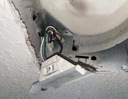
5 Now pry the electrical connection
box out and remove the wire nuts. If you didn't turn of the breaker, you can use a meter or a test light
to make sure the bare wires are not live, just in case.
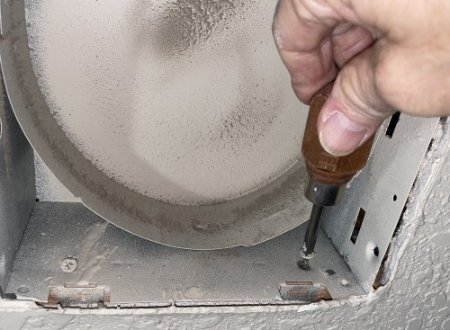
6 The housing should be attached
to a rafter by phillips head screws. You might need a short stubby screwdriver to get a good fit. Press hard,
so as not to strip the screw head!! And this is no place to use a cheap plastic phillips. If you strip these
screws. you will have to pry out the housing!
Some installers may have used screws with hex heads. You will need a nutdriver, small wrench,
or a 1/4in drive socket set to remove. These will actually be much easier to remove (but not if you attempt
to use pliers or an adjustable wrench). Time to go to the store and buy the proper tool!
7 In my case, the housing
would not budge even after removing the two screws, and there were none toward the top of the
housing. Further, the opposite side would move freely - so it was not attached.
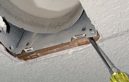
So this is the time to get a longer flat screwdriver and pry against the edge of the housing.
8 It gave way surprisingly easy,
revealing an additional screw that went through a tab on the housing. You can see the screw on
the lower right of the picture. Its head simply went through the tab (which probably had a
fairly large hole for this purpose).
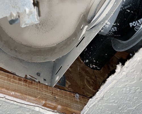
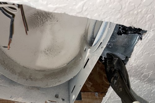
9 Well, here's a
hard part: removing the tape that wrapped the housing output and held it in the duct.
This is a tough tape! Make a cut in it first, using a sharp utility knife. (Keep your
other hand out of the way!) Then you can pull it partially off with pliers and then you should
be able to grip the tape and remove it.
This was rigid duct. If the duct is flexible, often the installer will simply have shoved it over
the housing outlet.
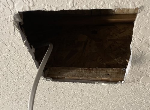
10 Pull the housing
out. It may be necessary to trim the edge of the sheetrock if the housing won't go through it.
The romex is shown here. (See the next picture, though).
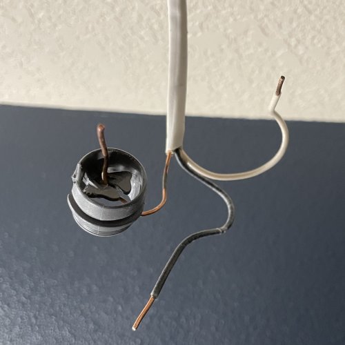
11 Couldn't pull the romex
out of the housing easily?? The plastic romex bushing shown here is why!! It has a slotted
piece of plastic which allows the romex to easily slide through during assembly but won't let it
be pushed out in the other direction. You can try to break away this internal plastic with a
small flat head screwdriver, to help in removing the romex.
If it just refuses to come out, AND there is excess romex, you can just cut it and then strip
the outer wrapping and expose about 3 inches of the individual conductors. Strip off about 1/2
inch of the insulation at the wire tips.
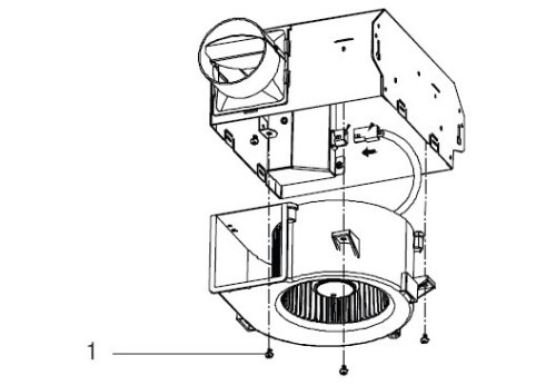
12 Remove the
black fan assembly from the metal housing before proceeding with the next steps. It's held
with 3 small screws. Put these three tiny but priceless screws in a bowl or some safe place!
I did not get a picture of this, so here is the image from step 5 of the "Existing construction"
section of the factory-supplied instruction sheet.
13
The fan enclosure has a removeable cable entrance bracket. While it is still
attached to the fan housing, use a flat screwdriver to remove one of the slotted "knockouts".
Do this before removing it from the housing. Why? Because the knockouts are pretty hard to
twist out. I removed the top knockout, since the romex cable comes in from the top (see #14).
Now remove the cable entrance bracket. Before passing the romex through it, press the original plastic
romex bushing through the knockout hole. Pry out the remains of the slotted plastic center so the
romex can easily pass through it. You are using the bushing to protect the romex from the possibly
sharp edges of the knockout hole. Using some sort of romex bushing makes for a much more
professional installation than simply passing romex through a knockout hole.
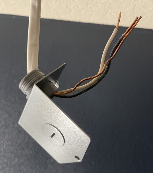
14 Now you can connect the
romex wires to the fan wires, using the quick connects. Usually it will be black-to-black, white-to-white,
and green wire-to-bare wire. The romex wires and the fan wires enter the same side of the quick
connects.
Re-attach the cable entrance bracket to the housing.
Before sliding the housing into the opening, attach the plastic outlet tube to the housing. You can
see the outlet tube in #15 below.
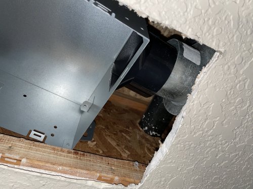
15 Place the housing up into
the hole. This particular fan is slightly bigger than the stock builder grade fan, and may require you
to trim away some sheetrock.
My original duct was solid. It slipped inside the black outlet of the fan. If you have flexible duct, it usually slips
over the black outlet. In most cases the duct will stay in place, especially when you push the housing toward
the duct. If you have flexible ducting and it seems too loose, you can use a large nylon wire tie to clamp it.
Yes, you can use duct tape to secure the flexible ducting to the fan outlet. But I can pretty much guarantee
that trying to work a piece of really sticky tape around the outlet in a confined space will prove to be really
frustrating!
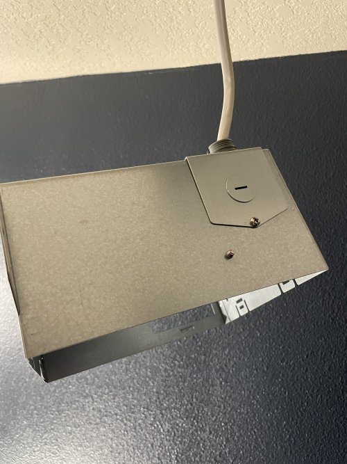
16 Here's the housing in place.
17 Now you can secure the housing
in place with two sheet metal screws. Some come with the fan kit. Otherwise some #8 sheet metal
screws, about an inch long, will work fine.
NOTE: I find that it is much easier to install screws if a pilot hole is drilled first. You might have to drill
at a bit of an angle because a standard drill may not fit in the opening, but that's OK. If you happen to
have an angle drill, you can drill straight holes with it. You will probably need to use a short stubby phillips
to tighten the screws. If you have some hex head sheet metal screws and a 1/4 inch socket wrench, you
can tighten these screws very easily.
Having installed two screws, you will probably find that the other side of the housing hangs below the
ceiling a bit. There is a third hole at the top, but most modern houses do not have solid joists any more!
As you can see in #15 above, the house has the "Wooden I-beam" joists. So there's no solid wood to hold a
screw. Solution: There are tabs on each side of the housing. You can see them in the back of this picture.
So raise the unsecured side a bit and bend these tabs out. They will then rest on the sheet rock.
18 Now comes the bane of every ceiling
light, ceiling fan, or exhaust fan project. You have to hold some sort of assembly upside down while trying to
line up 3 or more small screws, also upside down.
So put the black fan assembly into the housing and secure with the three screws. NOTE: You can see one
of the screws on the upper left, just to the right of the shiny wire connection housing.
(But check out these three tips first:)
It's a lot easier if your screwdriver is magnetized. if it isn't, you can draw it
repeatedly against a magnet (or buy a magnetized screwdriver!)
If the fan is above a lavatory, close the drain. If above the pot, close the seat.
Try to have the floor relatively clear of debris. We all know what happens to small parts
that are dropped on the floor! You're fighting the Law of Physics: "Every small part that is dropped will
seek the least visible spot or crevice, and will be nearly impossible to find." Corollary: "If it is a unique or
not easily replaced part, it will disappear from the face of the planet!"
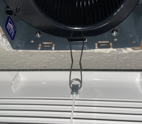
19 Now mount the grill, by
squeezing the spring holders. It's easier to do them one at a time
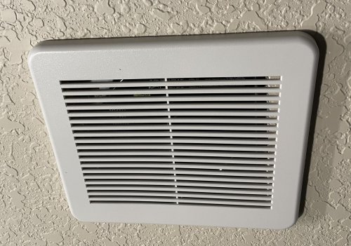
20 Here's the grill in place, and the
finished project.